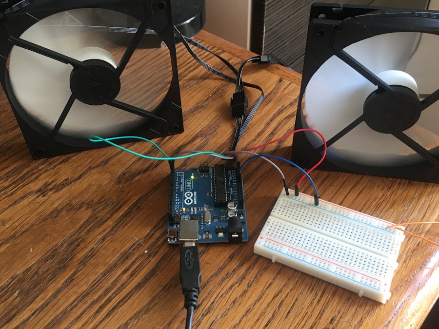
The rack is placed in a closed garage so the temperature range between winter and summer is pretty high and also dust could be a problem.
Arduino nano pwm fan control.
Temperature control with pid on arduino and pwm fans for diy server network rack cooling a few weeks ago i needed to setup a rack with network devices and a few servers.
I decided that i would like to have a programmable temperature based fan speed controller for a fume extractor i am building from scrap parts and the logical thing to do seemed to be to use an arduino nano as modern fans use a 5 volt pwm signal to control their speed and also report back their speed with another 5 volt signal.
Many projects that use a temp sensor but never the most simple thing.
According to the link here.
I had 5 laying around and thought mine as well give it a shot.
The frequency values can be adjusted between 125 hz 8 mhz as well as a variable duty cycle.
Beginner full instructions provided 24 154.
How pc fans work the three wire fan uses it s third wire to provide speed feedback tacho.
I have been wondering about this project and how to control my 4 pin pwm fans.
In the above wave forms you can see that the frequency is same but on time and off time are different two applications of pwm control using arduino is shown here.
For something that could perhaps work with the arduino you could build a circuit to convert the tacho output into a voltage and read it via the adc.
Firstly make sure that you fan s are pwm controller you can check this by making sure that your fan connector has 4 wires.
The arduino digital pins either gives us 5v when turned high or 0v when turned low and the output is a square wave signal.
Controlling the led brightness using arduino and motor speed control using arduino.
If they are pwm take a small flat headed screwdriver and pull the pwm pin out of the fan connector by pushing the metal part on top and pulling it back.
Hi nicolas if you want to do it accurately as david says you ll need different hardware.
Pwm stands for pulse width modulation and it is a technique used in controlling the brightness of led speed control of dc motor controlling a servo motor or where you have to get analog output with digital means.
Pwm waves with various duty cycle are shown in the figure below.
The circuit utilizes the mode 10 pwm phase correct on timer 1 ocr1a pin 9 and icr1 pin 10.
Control the speed of the fan.
There is some information out there.

